B.TECH R23 Network Analysis Important Questions
Note: Students, Always draw neat circuit diagrams and show step-by-step calculations to get good marks.
UNIT I
2 Marks Questions:
- State Reciprocity theorem.
- Explain the concept of source transformation with examples.
- What is the principle of duality? Give one example of dual circuits.
5 Marks Questions:
- Find the current through 6Ω resistor using Norton's theorem for the given circuit.

- Apply Substitution theorem to analyze a network with dependent sources.
- Determine the current through 2Ω resistor in the given circuit using appropriate method.

- Solve a circuit problem using Compensation theorem and verify with another method.
- Find the voltage across 20Ω resistor in the network using mesh analysis.

- Determine the Thevenin's equivalent of the given circuit.

UNIT II
2 Marks Questions:
- Write down few applications of RL, RC and RLC circuits.
- What is the significance of time constant in first order circuits?
- Define natural response and forced response in circuit analysis.
5 Marks Questions:
- Find the Laplace transform of the Half-wave rectifier function.
- Analyze a second order RLC circuit with AC excitation using s-plane concept.
- Consider the circuit shown below. The switch was in position S+ for a long time. It is operated as shown. Compute and plot the capacitor voltage for t > 0.Also find the time at which the capacitor voltage becomes zero.

- Apply Heaviside's expansion theorem to solve inverse Laplace transform problems.
- In an RL circuit having time constant 400ms the inductor current decays and its value at 500ms is 0.8A. Find the equation of iL(t) for t > 0.
- Find the Laplace transform of the periodic function given.


UNIT III
2 Marks Questions:
- Define phase difference in AC circuits.
- What is the physical significance of complex impedance?
- Explain the concept of phasor notation for AC analysis.
5 Marks Questions:
- Two impedances Z1 = 150 − j157Ω and Z2 = 100 − j110Ω. Find branch currents, total current, total power and draw vector diagram.

- Apply mesh analysis to solve AC circuits with multiple sources at different frequencies.
- A series circuit of resistance 10Ω, inductance 13mH and capacitance 150μF connected in series. A supply of 100V at 50Hz is given. Find impedance, current, pf and power.
- Convert a complex AC network from Star to Delta configuration and find equivalent impedance.
- Two parallel circuits comprising of a coil (20Ω, 0.07H) and a resistance (50Ω) in series with condenser (60μF) are connected across 230V, 50Hz. Calculate main current and power factor.

- Compute total Z and Y for the given complex AC circuit.

UNIT IV
2 Marks Questions:
- Define mutual inductance and its applications.
- What is the condition for maximum power transfer in resonant circuits?
- Explain the concept of bandwidth and selectivity in resonant circuits.
5 Marks Questions:
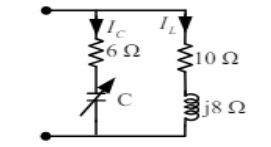
- Find the value of C for which the circuit is in resonance at 750Hz.
- Analyze anti-resonance condition in parallel circuits with resistance in both branches.
- The Q of a series circuit network is 10. The maximum amplitude of current at resonance is 1A when applied voltage is 10V. If L = 0.1H find the value of capacitance.
- Apply dot rule convention to solve magnetically coupled circuits with multiple loops.
- Determine the coupling coefficient and calculate the energy stored in the coupled inductors at time t = 1s.

- Find the value of L for which the circuit is in resonance at 1000Hz.

UNIT V
2 Marks Questions:
- What are the conditions for reciprocity for Z and Y parameters?
- Define propagation constant and its significance in network analysis.
- What is the difference between image impedance and iterative impedance?
5 Marks Questions:
- Find the y parameters for the two-port network shown.

- Design an impedance matching network for given source and load impedances.
- Obtain the hybrid (H) parameters of the given two-port network.

- Analyze the characteristics of lattice network and derive its parameters.
- For the network shown, show that AD - BC = 1.

- Select the values of RA, RB & RC in the circuit so that A = 1, B = 34Ω, C = 20mS and D = 1.4.
